How Are Components Verified For Compatability During Circuit Board Assembly?
Components Verified For Compatability During Circuit Board Assembly
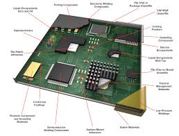
During circuit board assembly, components must be verified for compatibility. This is done through a variety of processes, from visual assessment to automated optical inspection (AOI) and even X-ray analysis. Ultimately, this step is designed to ensure the quality of the solder joints and overall assembly.
Choosing to work with a trusted printed circuit board assembly company rather than trying to do it yourself can make all the difference. Professionals will use the best materials and equipment for the job, helping to reduce the chances of error and resulting in a product that will function properly.
PCBs are usually made using a combination of through-hole and surface mount technology. The latter allows for more compact designs with fewer component parts and is a good choice for smaller components that are difficult to place using through-hole assembly methods. However, mixed-technology assembly can present challenges in terms of fabrication and assembly time, so it is important to consider design for manufacturability (DFM) during the layout stage.
How Are Components Verified For Compatability During Circuit Board Assembly?
A CAD system can be used to test the design before it goes to manufacturing, catching issues such as tolerances, compatibility, and component placement before they can cause problems in production. These systems can also generate Gerber files and other manufacturing-ready formats for quick transition to the manufacturing phase.
In addition to verifying the location of all the components, it is crucial to make sure that the footprints (patterns for how a component should be placed on the PCB) accurately reflect the specifications of the individual components. For example, polarized components like diodes and electrolytic or tantalum capacitors should include polarity indicators in their footprints to help assemblers identify the correct orientation. Additionally, pads should be sized correctly to prevent SMDs from moving during soldering.
Once the assembly process is complete, the finished product must undergo a series of inspections to confirm that it meets all necessary quality standards. These tests may be performed visually or with the help of dedicated fixtures. Dedicated fixtures can greatly reduce the testing time by automating the process and eliminating manual testing errors. However, this is an expensive investment that is only cost-effective when a significant quantity of units need to be tested.
Ideally, all defects should be caught during this stage of the assembly process to avoid introducing flawed products into the market. This is possible only if all phases of the assembly and inspection processes are executed correctly. An experienced contract electronics manufacturer will have a well-documented quality assurance process that includes all the required steps, from initial inspection to the final delivery of fully functional products to their clients.
Investing in a solid PCB manufacturing and assembly partner can save both money and time by reducing the chances of costly errors. A good contract electronics manufacturer will also be committed to a client-focused approach and maintain open communication with their customers. This helps to build a solid reputation as a reliable supplier of high-quality printed circuit boards.